
arrow_back
Back to articles list
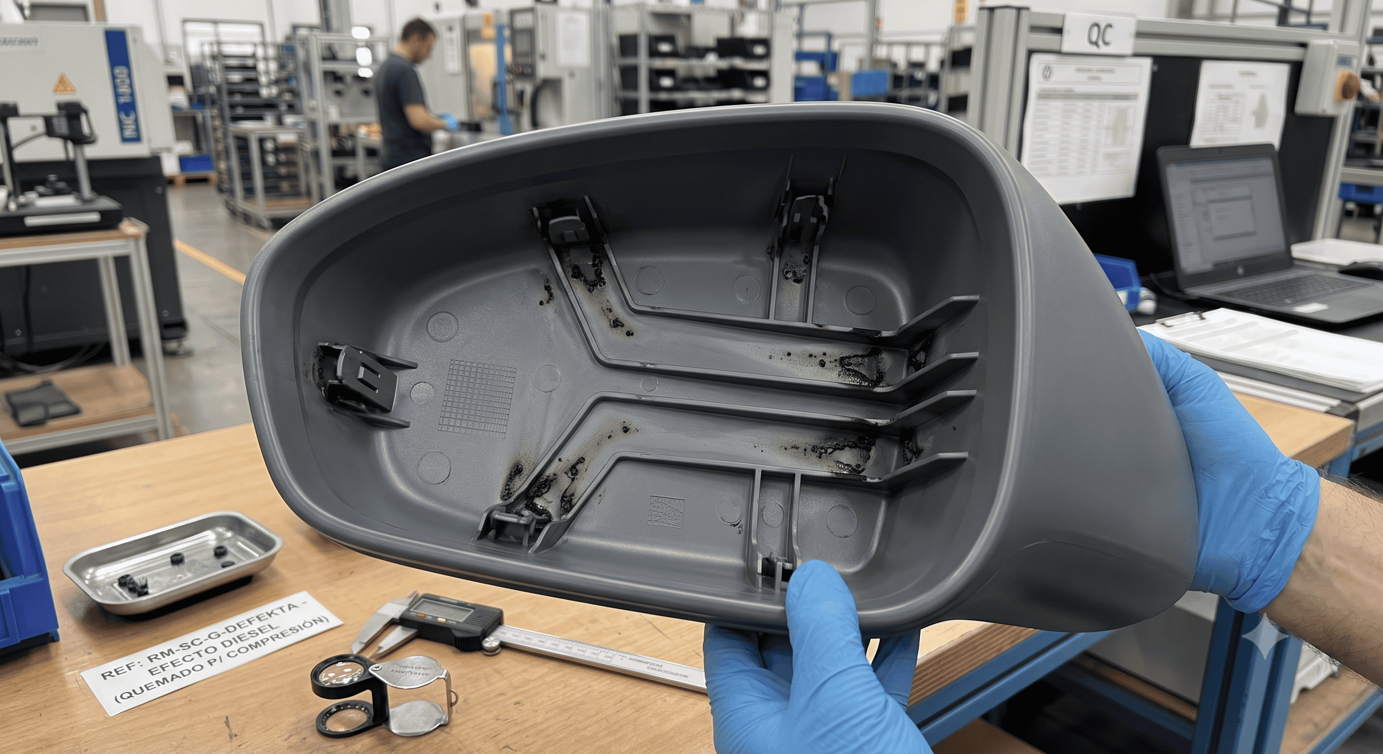
Diesel Effect on Injection Molding: Diagnosis, Numerical Simulation and Multidimensional Solutions
calendar_today
31/07/2026
The diesel effect, technically known in the manufacturing industry as gas trapping burn mark, is one of the most complex thermophysical instabilities in the injection molding process. This phenomenon not only compromises the aesthetic and structural quality of the plastic part but also prematurely degrades the steel in the mold cavities.
It all begins when the flow of molten polymer advances decisively through the mold cavity, displacing atmospheric air and volatile gases toward end zones or blind corners. Encountering insufficient or blocked exhaust pathways, this volume of air becomes trapped and undergoes violent compression driven by the enormous hydraulic energy of the injection unit, operating at pressures that typically range between 500 and 2000 bar. In a fraction of a second, classical thermodynamics takes over: the immediacy of the event prevents any significant heat exchange with the mold walls, triggering an adiabatic compression where the local air temperature rises sharply to between 400°C and 600°C. Under these extreme thermal conditions, oxygen triggers a spontaneous auto-ignition chemical reaction in the polymer matrix, carbonizing the material and releasing a sooty residue accompanied by a characteristic burnt charcoal odor.
To overcome this phenomenon known as the diesel effect, engineering employs a coordinated strategy that begins with adjusting the process itself: implementing multi-stage speeds by reducing injection by 15% to 40% in the final stage gives the gas the necessary time to filter out, while programming pressure switching between 95% and 98% of volumetric fill prevents destructive peaks, also allowing the plates to breathe by reducing the clamping force by 10% to 20%. In parallel, the mold architecture is optimized by machining active venting channels with depths of 0.008 to 0.013 mm for polyamides, utilizing the clearances of the ejector pins, incorporating porous sintered steel such as Porcerax II, or installing vacuum systems that extract air before filling to physically eliminate compression. The geometry of the part also plays a crucial role in guiding the polymer from thicker to thinner sections to prevent runout and in sizing the gates to prevent shear degradation. To protect the tooling, PVD chromium nitride coatings are applied as an inert barrier against corrosive gases, and ultrasonic cleaning with acetone is performed every 15,000 to 30,000 cycles. Finally, predictive simulation in Moldflow or Moldex3D using coupled 3D analysis and the Modified Cross rheological model allows for the virtual anticipation of these transient peaks before metal cutting, ensuring stable production. Technical details, equations, and step-by-step guides can be downloaded free of charge from www.calcamsl.com.
Need to solve a specific technical issue or go deeper into this manufacturing process?
This article is just an executive summary. Download the Extended Technical Paper (PDF) with full diagrams, material charts, production tolerances, and step-by-step failure analysis.